Making an electronic drum kit
We decided for Christmas 2018 to make presents. Of course this meant I had to escalate things and I spent loads of time on this project. It was great fun though and I learned a lot doing it. Plus I only burned one finger with the soldering iron.
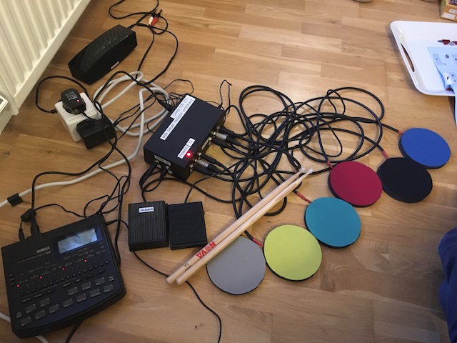
My son is learning drums so I thought I would have a go at making an electronic drum kit. The basic idea is to have a set of pads that you can hit with real drum sticks but which make no noise themselves. The pads measure how hard you hit them and connect to a box to turn the ‘I’ve been hit’ signals into MIDI messages. The MIDI messages are sent to a cheap drum machine I found on eBay. The drum machine makes drum noises into headphones, so we can all be in the house without being deafened by drums. The bit in the middle that turns drum hits into MIDI messages is actually a real thing that musicians use that you can buy, if you have the money, like this: https://www.gear4music.com/Drums-and-Percussion/DDrum-DDTI-Drum-Trigger-Interface/2MB9.
I thought I would post showing what I’ve built and how I put it together, along with the very helpful blog posts that showed the way.
Research and planning
This tutorial from Sparkfun shows the basic principal: https://www.sparkfun.com/tutorials/330. It uses an Arduino to measure the signal from the Piezo. I was originally going to make a bare bones electronics bundle and leave it at that, but no, I had to go further.
I came across this post: Spooky Arduino Projects which really shows the way. By sandwiching the sensor between two mouse mat circles you can create a tough mat that you can hit with drum sticks. You can also make the Arduino emit MIDI really easily, since the Arduino can send serial signals from the digital output pins.
This post: https://www.instructables.com/id/MIDI-Arduino-Drums/ was really helpful in designing the kit and building the pads. It also had links to some really good Arduino sketches (software for Arduino is called a sketch).
I was originally thinking of using a Raspberry Pi to make the drum sounds but luckily I decided that was going to be too much effort - I bought a cheap drum machine off eBay instead. Vintage 1992, the Yamaha RY-10: http://www.muzines.co.uk/articles/yamaha-ry10-drum-machine/2345.
Let’s make this!
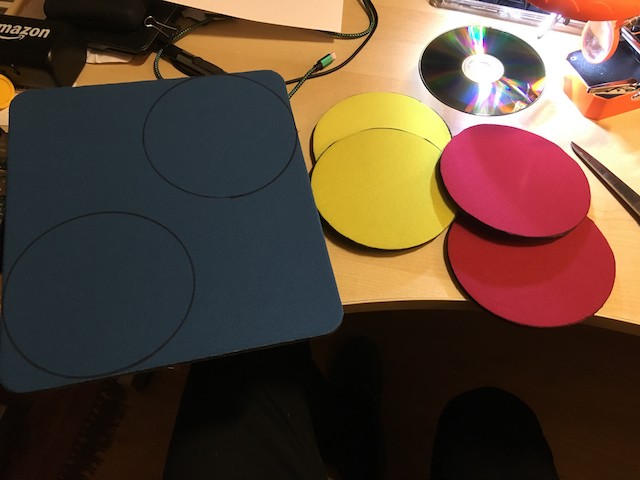
First I had to make the pads. To start I cut circles from mouse mats.
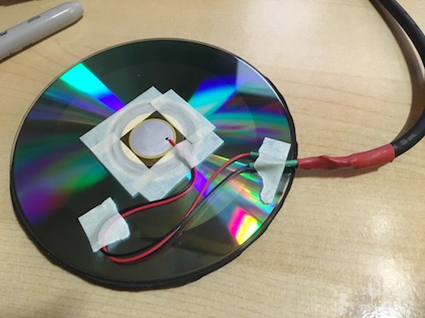
Then, after soldering the piezo sensor to a shielded cable, I taped the sensor to the middle of an old CD.
I used superglue to sandwich the cd between two of the mouse mat disks.
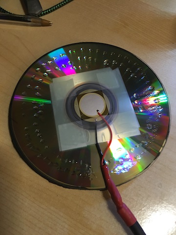
Finally I soldered a 1/4” jack onto the end of the shielded cable. This is actually a fairly standard musical instrument connection.
Prototype
Before going further I wanted to test the concept worked so I built a prototype using the todbot.com blog earlier.
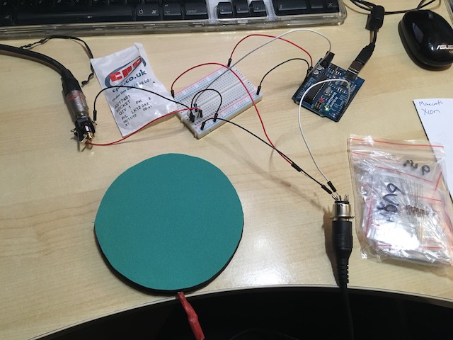
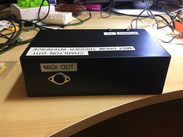
In the picture you can see the first pad that I made, with the 1/4” jack plugged into a jack socket. The socket is wired to a circuit on the breadboard and ultimately connected to the analog input pins of the Arduino. I’ve also connected a 5-pin DIN socket to the serial output of the Arduino to create a MIDI port. I’ve plugged a MIDI cable into this and the other end plugged into my Alesis MIDI keyboard. The keyboard is playing the part of the drum machine in my prototype.
I loaded the Arduino with this sketch https://todbot.com/arduino/sketches/midi_drum_kit/midi_drum_kit.pde - though you have to adjust the pin numbers in the sketch to match which pins you have connected to. Also note the sketch uses MIDI channel 1, whereas drums are normally on channel 10. After fiddling with these values a bit, it started working! I hit the pad, drum sounds came from my keyboard. It was going to work!
Productizing
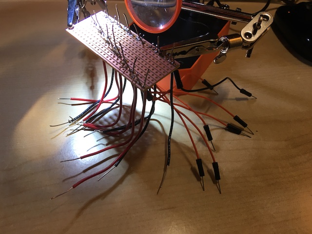
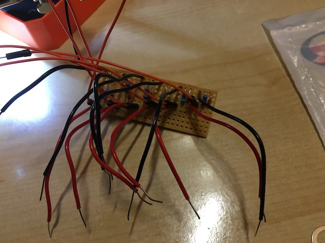
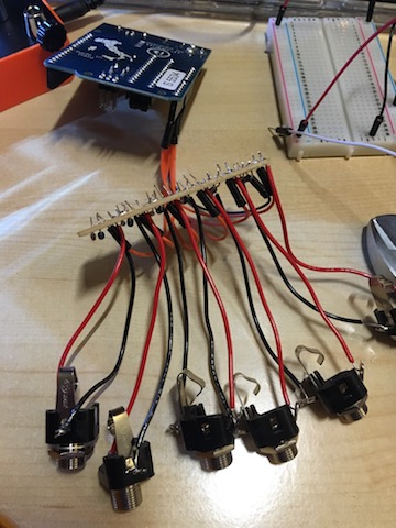
Now I knew the idea would work, I started to plan how the finished product might look. The Arduino I was using had 6 analog inputs, so I could connect at most 6 drum pads. The little circuit on the breadboard is to protect the Arduino from the voltage that the piezo sensor generates. So for 6 pads I would need to repeat the circuit 6 times and have 6 jack sockets. That’s a fair bit of wiring as I quickly discovered. I didn’t think the breadboard would be robust enough so I ordered some veroboard and soldered 6 copies of the protection circuit to it like this. Yes, I know my soldering isn’t going to win any awards, but I hadn’t done it before.
Pedals
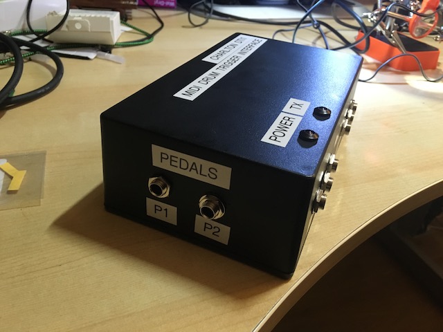
Now I could make 6 pads, which would already have been a fairly decent drum collection. But everytime I showed this to someone they asked me where would the pedals for bass drum and hi-hat come into it. I thought about wiring a piezo to a real drum pedal, but real drum pedals seemed to be really expensive. Then I would still need to rig up something for the pedal to hit. This sounded like too much work to get done. I already had a sustain pedal for my keyboard which I wasn’t using, so I wondered if I could use that. Turns out that electronic keyboard sustain pedals tend to all work in the same way - they’re effectively a big switch that ends in the ubiquitous 1/4” jack. If I wired these to the digital inputs of the Arduino then I could get pedal input. The only drawback is that these are not velocity sensitive, but I thought that was a good compromise for a pedal. I ordered another cheap sustain pedal. Now I could have 8 velocity sensitive pads and two pedals. By sheer luck I had enough for a complete drum kit: bass drum (pedal), snare, high tom, low tom, floor tom, crash cymbal, ride cymbal and hi-hat (pedal).
More circuits
To wire in the pedals I added some more circuitry. I wanted to at least try and protect in case someone plugged a piezo-based pad into the pedal ports. I also wanted an LED to show when the circuit was sending a drum hit, just because I like having flashing lights on things. Cue me soldering a second piece of veroboard. This time I managed to burn my finger on the soldering iron. Nothing like the smell of burning flesh to make you wonder, “why am I doing this again?”.
The box
I realised that I couldn’t hand over a wired together bunch of circuits and expect it to last in front of a kid wielding drum sticks. I had to put all the electronics into a box. I thought the box should have a power light and an on / off switch too. Here I learned that a combination of my amateur soldering, solid core wires and poor planning meant there was no way the whole thing would squeeze into a tiny box. I had to go for a large box but found it still wouldn’t fit. So after that I had to go larger still. Hence the rather large dimensions of this beast.
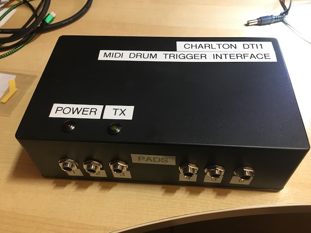
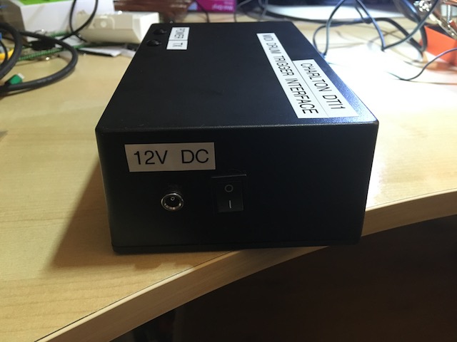
To complete the box I ordered a power socket, power switch and two led holders. Putting this together involved a fair bit of Dremel action.
Coding
Up until this point the Arduino code from the todbot blog I was using was a bit unreliable. It uses delay() to sleep for short periods which might just about work for one drum pad but doesn’t work for lots being hit at the same time. Luckily the code from the Instructables post is better designed. It doesn’t have any delay() code and just continuously loops reading the state of the pads. I was able to adapt this code by adjusting all the pin numbers, matching the notes to be played to the RY-10 drum machine, and also to add code for the drum pedals.
//Xylophone
//Adapted for an ArduinoMega
//from Jenna deBoisblanc and Spiekenzie Labs initial code

//*******************************************************************************************************************
// User settable variables
//*******************************************************************************************************************

int pinRead;
// On the Yamaha RY10 this amounts to:
// Pads 1-6 play: SD1 (C), SD2 (D), TOM1 (E), TOM2 (F), RIDE (K), CRASH (L)
// Pedals 1-2 play: BD1 (A), HH CLOSE1 (H)
byte PadNote[8] = {
  38,40,50,47,51,49,35,42};         // MIDI notes from 0 to 127 (Mid C = 60)
int PadCutOff[6] =
{
  70,70,70,70,70,70};           // Minimum Analog value to cause a drum hit
int MaxPlayTime[8] = {
  90,90,90,90,90,90,200,200};               // Cycles before a 2nd hit is allowed
#define  midichannel 9;                              // MIDI channel from 0 to 15 (+1 in "real world")
boolean VelocityFlag  = true;                           // Velocity ON (true) or OFF (false)

//*******************************************************************************************************************
// Internal Use Variables
//*******************************************************************************************************************
boolean activePad[8] = {
  0,0,0,0,0,0,0,0};                   // Array of flags of pad currently playing
int PinPlayTime[8] = {
  0,0,0,0,0,0,0,0};                     // Counter since pad started to play
byte status1;

int pin = 0;
int hitavg = 0;

// define the pins we use
#define switchAPin 7
#define switchBPin 6
#define ledNotePin     4  // for midi out status
#define ledPowerPin     5  // to show we're on

//*******************************************************************************************************************
// Setup
//*******************************************************************************************************************
void setup()
{
  pinMode(switchAPin, INPUT);
  pinMode(switchBPin, INPUT);
  digitalWrite(switchAPin, HIGH);  // turn on internal pullup
  digitalWrite(switchBPin, HIGH);  // turn on internal pullup

  pinMode(ledNotePin, OUTPUT);
  pinMode(ledPowerPin, OUTPUT);
  digitalWrite(ledPowerPin,HIGH);  // indicate we're sending MIDI data

  Serial.begin(31250);                                  // SET HAIRLESS TO THE SAME BAUD RATE IN THE SETTINGS

}
//*******************************************************************************************************************
// Main Program
//*******************************************************************************************************************
void loop()
{
  // deal with the analog pads
  for(int pin=0; pin < 6; pin++)                          //
  {
    hitavg = analogRead(pin);
    // read the input pin

    if((hitavg > PadCutOff[pin]))
    {
      if((activePad[pin] == false))
      {
        if(VelocityFlag == true)
        {
          hitavg = (hitavg / 8) -1 ;               // Upper range
        }
        else
        {
          hitavg = 127;
        }
        MIDI_TX(144,PadNote[pin],hitavg); //note on

        PinPlayTime[pin] = 0;
        activePad[pin] = true;
      }
      else
      {
        PinPlayTime[pin] = PinPlayTime[pin] + 1;
      }
    }
    else if((activePad[pin] == true))
    {
      PinPlayTime[pin] = PinPlayTime[pin] + 1;
      if(PinPlayTime[pin] > MaxPlayTime[pin])
      {
        activePad[pin] = false;
        MIDI_TX(144,PadNote[pin],0);
      }
    }
  }
  // deal with the switches
  handle_switch_pin(switchAPin);
  handle_switch_pin(switchBPin);
  boolean active = false;
  for(int pin=0; pin < 8; pin++)
  {
    if (activePad[pin] == true) {
      active = true;
    }
  }
  if (active == true) {
    digitalWrite(ledNotePin,HIGH);  // indicate we're sending MIDI data
  } else {
    digitalWrite(ledNotePin,LOW);
  }
}

void handle_switch_pin(int pin)
{
  int currentSwitchState = digitalRead(pin);
  if (!activePad[pin] && currentSwitchState == LOW) {
    activePad[pin] = true;
    PinPlayTime[pin] = 0;
    MIDI_TX(144,PadNote[pin],127); //note on
  } else if (activePad[pin]) {
    PinPlayTime[pin] = PinPlayTime[pin] + 1;
    if(PinPlayTime[pin] > MaxPlayTime[pin]) {
      MIDI_TX(144,PadNote[pin],0); //note off
      if (currentSwitchState == HIGH) {
        activePad[pin] = false;
      }
    }
  }
}

//*******************************************************************************************************************
// Transmit MIDI Message
//*******************************************************************************************************************
void MIDI_TX(byte MESSAGE, byte PITCH, byte VELOCITY)
{
  status1 = MESSAGE + midichannel;
  Serial.write(status1);
  Serial.write(PITCH);
  Serial.write(VELOCITY);
}
End result
I surprised myself in the end and was really pleased how well this turned out. I think my son liked it too. I may let him play on it occasionally :)